Engine Management · Technical Specification
Standalone Engine Management ECU
A from-scratch automotive ECU that drives fuel injectors and ignition coils directly, runs closed-loop on engine sensors, and covers 4-, 6- and 8-cylinder engines from a single board — with both USB-C and Bluetooth as full firmware-flashing paths.
- Board
- 165.8 × 130.2 mm
- Stackup
- 8 layers
- Components
- 224
- Nets
- 236
- Cylinders
- 4 / 6 / 8
In development — design complete, not yet built. The schematic and PCB are finished, fully routed and pass electrical- and design-rule checks, but no board has been fabricated, assembled, powered or run on an engine, and the bill of materials is not yet costed. Nothing here is a tested or purchasable product.
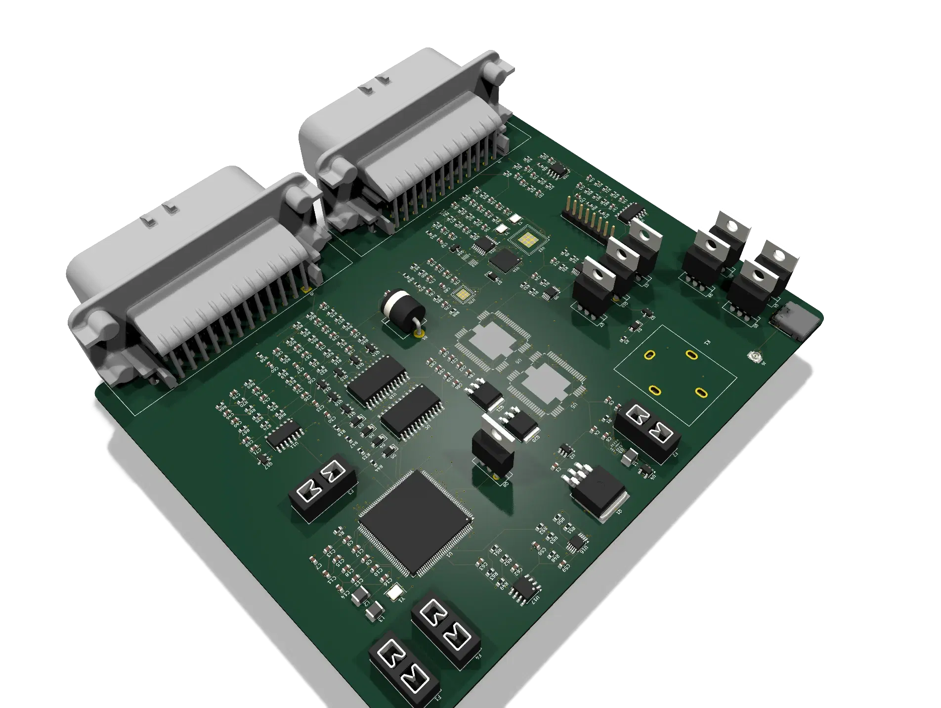
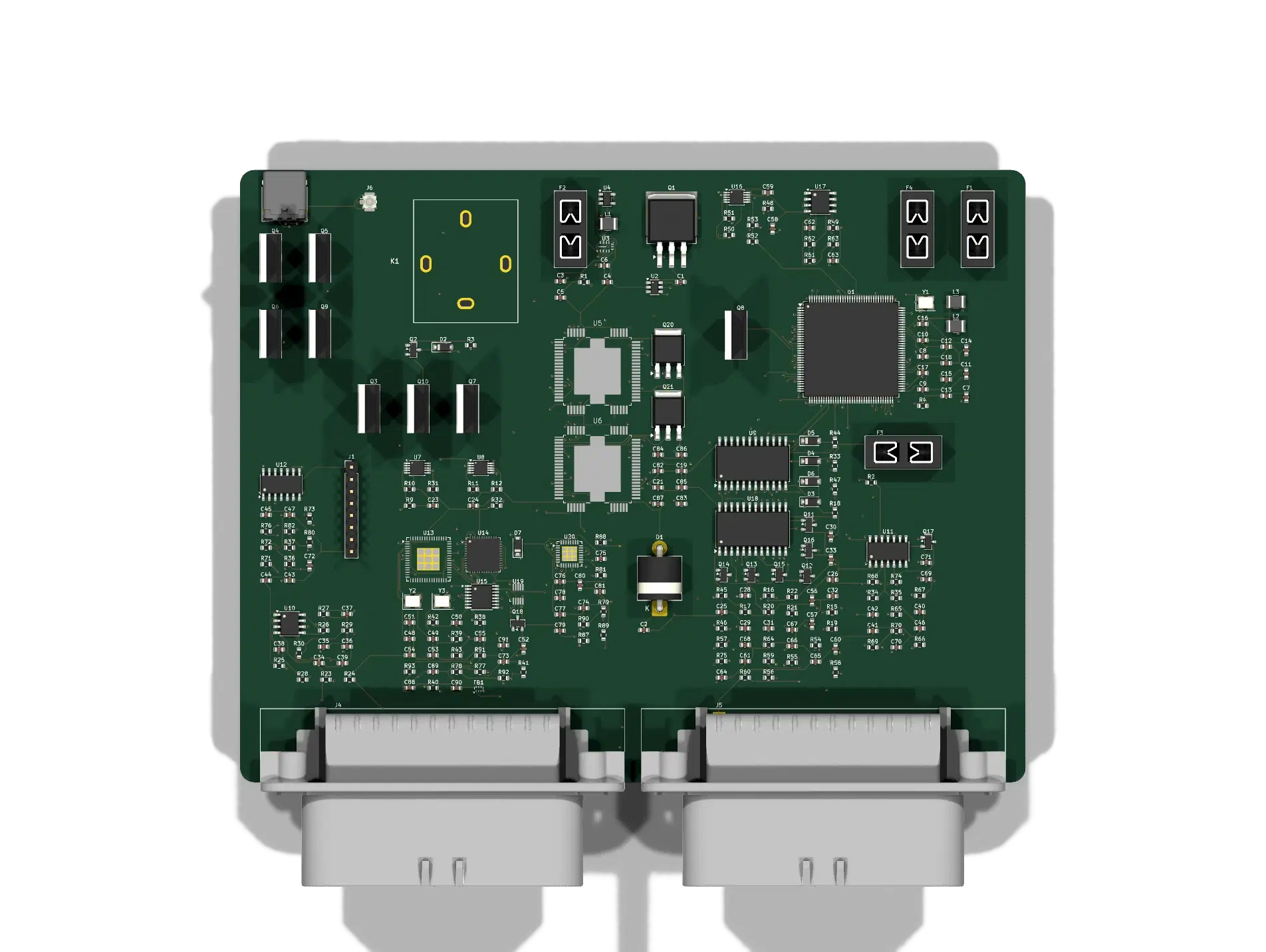
At a glance
Engine control
Sequential injection and per-cylinder ignition, with cam phasing measured on two independent hardware capture channels — enough for a DOHC engine varying intake and exhaust timing separately.
| Function | Ch. | Implementation |
|---|---|---|
| Fuel injection | 8 | Sequential low-side drive — 2 × NXP MC33810 |
| Ignition | 8 | Per-cylinder IGBT — 8 × ON Semi FGP3040G2, MC33810 gate drive |
| Crank position | 1 | Variable-reluctance, hardware input capture — MAX9924 |
| Cam position | 2 | Independent intake / exhaust capture — 2 × MAX9924 |
| Cam phaser control | 2 | PWM solenoid drive, flyback clamped |
| Overcurrent protection | — | Autonomous per-chip latch-off; no firmware involvement |
Sensor inputs
| Input | Ch. | Front end |
|---|---|---|
| Manifold pressure (MAP) | 1 | RC-filtered analogue |
| Throttle position (TPS) | 1 | RC-filtered analogue |
| Intake air temp (IAT) | 1 | NTC pull-up divider |
| Coolant temp (CLT) | 1 | NTC pull-up divider |
| Oil pressure | 1 | RC-filtered analogue — enables low-pressure protection |
| Fuel pressure | 1 | RC-filtered analogue — enables pressure-loss protection |
| Battery voltage | 1 | Divider, ~25.7 V full scale — a 24 V jump-start still reads on-scale |
| Knock | 2 | One per bank — 2 × TI TLV2372-Q1 |
| Wideband oxygen | 2 | One per bank, Bosch LSU 4.2 / 4.9 — 2 × Bosch CJ125 + heater drive |
| Exhaust gas temp (EGT) | 1 | Type-K thermocouple read directly by a differential ADC over SPI, with cold-junction compensation and linearization in firmware — Texas Instruments ADS1118-Q1 |
| Flex-fuel (ethanol %) | 1 | Frequency/duty capture, open-collector sensor pulled to 3.3 V |
Actuator outputs
Measuring cam phase is only useful if the phasers can also be driven — all six outputs are MOSFET low-side with Schottky flyback clamps.
| Output | Ch. | Type |
|---|---|---|
| Cam phaser solenoids (VVT) | 2 | PWM |
| Idle air valve | 1 | PWM |
| Fuel pump relay | 1 | Switched |
| Tachometer | 1 | Open-drain signal, pulled to 5 V |
| Main power relay | 1 | Switched, gates the whole power stage |
| Boost control solenoid | 1 | PWM, flyback clamped — wastegate or boost-control valve |
Electronic throttle control
Drive-by-wire, with the redundant sensing a safety-critical throttle needs: two independent readings on the pedal and two on the throttle body, so the firmware can cross-check for an implausible signal before trusting it.
| Function | Ch. | Implementation |
|---|---|---|
| Pedal position | 2 | Independent redundant sensors — APP1 / APP2 |
| Throttle body position | 2 | Independent redundant sensors — TPS1 / TPS2 |
| Motor drive | 1 | H-bridge, current-sense feedback to the MCU — NXP MC33926 |
| Hardware disable | 2 | Independent of the PWM path — one active-high, one active-low |
The board provides the redundant sensing and an independent hardware cutoff. Deciding when the two readings disagree enough to disable the motor is firmware's job — this is not a certified drive-by-wire safety system on its own.
Communications & programming
Both flashing paths are complete reflash paths, not telemetry. They share the bootloader lines through an analogue switch, so plugging in USB automatically takes priority — no firmware decision, no mode button.
| Interface | Detail |
|---|---|
| CAN | 2 independent buses, split termination, wakes with ignition off — 2 × NXP TJA1043T |
| USB-C | Bootloader UART plus JTAG debug — FTDI FT4232HA |
| Bluetooth LE | Full over-the-air firmware reflash — TI CC2640R2F-Q1 |
| Bus arbitration | USB takes priority automatically when connected — TI SN3257-Q1 |
| Antenna | U.FL external — suits a metal enclosure |
| Bench debug | Dedicated JTAG header |
Power
| Stage | Detail |
|---|---|
| Input protection | Reverse-battery and load-dump — LM74700-Q1 ideal-diode controller + 100 A MOSFET + TVS |
| 5 V rail | Buck regulator, sensors and analogue — TI LMR33630-Q1 |
| 3.3 V rail | LDO, MCU and logic — TI TLV733P-Q1 |
| Power stage | Relay-gated, separately fused injector and ignition rails (4 × mini blade) |
Harness connectors
Two 35-way TE AMPSEAL 776180-1 connectors, split by function the way a production ECU splits them. Physical layout is the connector's own real numbering — the centre row is staggered a half-pitch relative to the outer rows, not a simplification: pins run left–to–right along the top row, then the staggered middle row, then the bottom row. “Connects to” traces each signal through its real front-end IC or, where it reaches the MCU with only a passive filter in between, the real silicon pin.
J4 — Engine harness
35-position · 3-row · 4 mm pitch · right-angle THT · 33 of 35 cavities used · 2 spare
| Pin | Signal | Direction | Connects to | Notes |
|---|---|---|---|---|
| 1 | VIN | Power in | Q1/D1/U2 reverse-battery + load-dump stage | Upstream of F1 (30A automotive fuse). |
| 2 | GND | Ground | Chassis / battery negative | — |
| 3 | GND | Ground | Chassis / battery negative | — |
| 4 | VBATT_INJ | Power out | F3 fuse output (15A) | Feeds MC33810 #1/#2 VPWR, upstream of the injector low-side drivers. |
| 5 | INJ1_LO | Actuator out | MC33810 #1 (U5) OUT0 | Sequential low-side injector drive. |
| 6 | INJ2_LO | Actuator out | MC33810 #1 (U5) OUT1 | — |
| 7 | INJ3_LO | Actuator out | MC33810 #1 (U5) OUT2 | — |
| 8 | INJ4_LO | Actuator out | MC33810 #1 (U5) OUT3 | — |
| 9 | INJ5_LO | Actuator out | MC33810 #2 (U6) OUT0 | — |
| 10 | INJ6_LO | Actuator out | MC33810 #2 (U6) OUT1 | — |
| 11 | INJ7_LO | Actuator out | MC33810 #2 (U6) OUT2 | — |
| 12 | INJ8_LO | Actuator out | MC33810 #2 (U6) OUT3 | — |
| 13 | VBATT_IGN | Power out | F4 fuse output (25A) | Feeds the 8 ignition IGBT collectors, separately fused from the injector rail. |
| 14 | IGN1_COIL | Actuator out | Q3 IGBT collector | Gate driven by MC33810 #1 GD0, real-time firing from MCU eMIOS via DIN/GIN. |
| 15 | IGN2_COIL | Actuator out | Q4 IGBT collector | — |
| 16 | IGN3_COIL | Actuator out | Q5 IGBT collector | — |
| 17 | IGN4_COIL | Actuator out | Q6 IGBT collector | — |
| 18 | IGN5_COIL | Actuator out | Q7 IGBT collector | Gate driven by MC33810 #2 GD0. |
| 19 | IGN6_COIL | Actuator out | Q8 IGBT collector | — |
| 20 | IGN7_COIL | Actuator out | Q9 IGBT collector | — |
| 21 | IGN8_COIL | Actuator out | Q10 IGBT collector | — |
| 22 | CRANK_VR_HI | Sensor in | MAX9924 crank interface (U7) | Variable-reluctance sensor pair. |
| 23 | CRANK_VR_LO | Sensor in | MAX9924 crank interface (U7) | — |
| 24 | CAM_VR_HI | Sensor in | MAX9924 intake-cam interface (U8) | — |
| 25 | CAM_VR_LO | Sensor in | MAX9924 intake-cam interface (U8) | — |
| 26 | CAM2_VR_HI | Sensor in | MAX9924 exhaust-cam interface (U16) | Second cam channel - independent intake/exhaust phasing on a DOHC engine. |
| 27 | CAM2_VR_LO | Sensor in | MAX9924 exhaust-cam interface (U16) | — |
| 28 | TPS1_SIG | Sensor in | RC filter → MCU pin 70 (ADC0_P11_TPS1) | Redundant throttle-body position sensor 1 of 2 - electronic throttle control. |
| 29 | TPS2_SIG | Sensor in | RC filter → MCU pin 71 (ADC0_P12_TPS2) | Redundant throttle-body position sensor 2 of 2. |
| 30 | ETC_MOTOR_A | Actuator out | MC33926 H-bridge (U20) OUT1 | Throttle-body motor drive, one of two leads. |
| 31 | ETC_MOTOR_B | Actuator out | MC33926 H-bridge (U20) OUT2 | Throttle-body motor drive, other lead. |
| 32 | BOOST_OUT | Actuator out | Q18 MOSFET drain | Gate driven by MCU pin 109 (E1UC19_BOOST) - wastegate / boost-control solenoid. |
| 33 | +5V | Power out | Regulated 5V rail | Dedicated excitation feed for the throttle-body TPS1/TPS2 potentiometers. |
| 34 | — | Spare | — | — |
| 35 | — | Spare | — | — |
J5 — Sensor & CAN harness
35-position · 3-row · 4 mm pitch · right-angle THT · 35 of 35 cavities used · 0 spare
| Pin | Signal | Direction | Connects to | Notes |
|---|---|---|---|---|
| 1 | +5V | Power out | Regulated 5V rail | Sensor excitation - MAP/TPS/IAT/CLT/APP1/APP2 dividers. |
| 2 | GND | Ground | Chassis / sensor return | — |
| 3 | MAP_SIG | Sensor in | RC filter → MCU pin 72 (ADC0_MAP) | — |
| 4 | TPS_SIG | Sensor in | RC filter → MCU pin 75 (ADC0_TPS) | Conventional single-channel throttle input - a separate, legacy signal from the redundant TPS1/TPS2 pair on J4. |
| 5 | IAT_ADC | Sensor in | NTC pull-up divider → MCU pin 76 | Intake air temperature. |
| 6 | CLT_ADC | Sensor in | NTC pull-up divider → MCU pin 77 | Coolant temperature. |
| 7 | KNOCK_SIG | Sensor in | TLV2372 op-amp (U10) → MCU pin 53 | Knock sensor, bank 1. |
| 8 | O2_UN | Sensor in | Bosch CJ125 #1 (U9) Nernst input | Wideband O2, bank A - real LSU 4.2/4.9 sensor wire. |
| 9 | O2_IP | Sensor in | Bosch CJ125 #1 (U9) pump current | — |
| 10 | O2_IA | Sensor in | Bosch CJ125 #1 (U9) trim/calibration | — |
| 11 | O2_VM | Sensor in | Bosch CJ125 #1 (U9) virtual ground | — |
| 12 | OILP_SIG | Sensor in | RC filter → MCU pin 64 (ADC0_P5_OILP) | Enables low-oil-pressure protection. |
| 13 | HTR_DRAIN | Actuator out | Q11 MOSFET drain | O2 bank-A heater, gate driven by MCU pin 12 (GPIO_HTR_CTRL). |
| 14 | VBATT_SW | Power out | Relay-switched battery (K1) | Common feed for every solenoid/relay driven by the *_OUT low-side pins below. |
| 15 | CAN0_H | Comms | CAN transceiver → MCU pins 28/27 | FlexCAN pair 1. |
| 16 | CAN0_L | Comms | CAN transceiver → MCU pins 28/27 | — |
| 17 | CAN1_H | Comms | CAN transceiver → MCU pins 117/116 | FlexCAN pair 2, fully independent bus. |
| 18 | CAN1_L | Comms | CAN transceiver → MCU pins 117/116 | — |
| 19 | FUELP_SIG | Sensor in | RC filter → MCU pin 65 (ADC0_P6_FUELP) | Enables fuel pressure-loss protection. |
| 20 | KNOCK2_SIG | Sensor in | TLV2372 op-amp (U17) → MCU pin 66 | Knock sensor, bank 2. |
| 21 | O2B_UN | Sensor in | Bosch CJ125 #2 (U18) Nernst input | Wideband O2, bank B. |
| 22 | O2B_VM | Sensor in | Bosch CJ125 #2 (U18) virtual ground | — |
| 23 | O2B_IP | Sensor in | Bosch CJ125 #2 (U18) pump current | — |
| 24 | O2B_IA | Sensor in | Bosch CJ125 #2 (U18) trim/calibration | — |
| 25 | HTR2_DRAIN | Actuator out | Q17 MOSFET drain | O2 bank-B heater, gate driven by MCU pin 88 (GPIO_HTR2_CTRL). |
| 26 | VVT1_OUT | Actuator out | MOSFET gate ← MCU pin 129 (E0UC19_VVT1) | Cam phaser solenoid 1, PWM. |
| 27 | VVT2_OUT | Actuator out | MOSFET gate ← MCU pin 132 (E0UC20_VVT2) | Cam phaser solenoid 2, PWM. |
| 28 | IDLE_OUT | Actuator out | MOSFET gate ← MCU pin 133 (E0UC21_IDLE) | Idle-air valve, PWM. |
| 29 | FPUMP_OUT | Actuator out | Relay ← MCU pin 67 (GPIO_FPUMP) | Fuel pump, switched. |
| 30 | TACH_OUT | Actuator out | Q16 MOSFET ← MCU pin 84 (E0UC25_TACH) | Open-drain tachometer signal. |
| 31 | APP1_SIG | Sensor in | RC filter → MCU pin 68 (ADC0_P9_APP1) | Redundant accelerator pedal position 1 of 2 - electronic throttle control. |
| 32 | APP2_SIG | Sensor in | RC filter → MCU pin 69 (ADC0_P10_APP2) | Redundant accelerator pedal position 2 of 2. |
| 33 | EGT_TC_P | Sensor in | ADS1118-Q1 (U19) AIN0 | Type-K thermocouple, positive leg. |
| 34 | EGT_TC_M | Sensor in | ADS1118-Q1 (U19) AIN1 | Type-K thermocouple, negative leg. |
| 35 | FLEXFUEL_SIG_RAW | Sensor in | Pull-up/filter → MCU pin 103 (E1UC20_FLEXFUEL) | Open-collector flex-fuel sensor - frequency = ethanol %, duty cycle = fuel temp. |
TPS_SIG and TPS1/TPS2 are not the same signal
J5 pin 4 (TPS_SIG) is the original single-channel throttle input from a conventional cable-actuated throttle body. J4 pins 28/29 (TPS1/TPS2) are the new, independent redundant pair for electronic throttle control. Both exist on this board; only one set applies depending on which throttle body is actually wired up.
VBATT_SW is switched, not raw battery
J5 pin 14 passes through the main relay (K1) — it is live only when the relay is energized, unlike J4 pin 1 (VIN), which is always live off the battery through the reverse-battery protection stage. Every solenoid and heater on J5 draws from this switched rail.
Injector and ignition rails are separately fused
VBATT_INJ (J4 pin 4) runs through a 15 A fuse (F3); VBATT_IGN (J4 pin 13) runs through a 25 A fuse (F4) — sized independently per the real worst-case draw of each rail, not a single shared fuse for both.
Two independent +5 V feeds
J4 pin 33 and J5 pin 1 are both regulated +5 V, but serve different sensor groups (throttle-body pots vs. the MAP/TPS/IAT/CLT/pedal dividers) — real, separate traces back to the same regulator, not a single shared harness pin.
Hardware
| Item | Specification |
|---|---|
| Microcontroller | NXP MPC5606B, 144-LQFP, Power Architecture — 1 MB flash, 80 KB RAM, eMIOS timer coprocessor |
| Timer capacity | 25 of 64 eMIOS channels used — injection, ignition, crank, cam, VVT, idle, tach, boost, flex-fuel, throttle drive |
| PCB | 165.8 × 130.2 mm, 8 layers, 4 signal layers each against a reference plane |
| Planes | 3 × ground, 1 × 3.3 V |
| Qualification | Automotive-rated (AEC-Q100 / Q101 / Q200) throughout |
| Spare capacity | 2 harness cavities, 59 microcontroller pins, 39 timer channels |
Known limitations
Recorded openly rather than discovered later.
- Before fabNo costed bill of materials. Parts are chosen and datasheet-verified, but not yet priced or checked for distributor stock.
- By choiceNo per-channel diagnostics on the actuator outputs. Discrete MOSFETs were chosen over an integrated driver to avoid introducing an unverified part; the trade is no open-load or short reporting on those six outputs.
- By choice10- and 12-cylinder engines are not supported. The microcontroller has ample headroom, but a third driver chip and four more IGBTs would consume the remaining engine-harness cavities for a small slice of the market.
- UnverifiedTwo Bluetooth details need confirming at bring-up. The radio's UART and boot pin assignments, and the antenna matching values.
- UnverifiedITS-90 Type-K linearization is not yet implemented in firmware. The EGT front end (ADS1118-Q1) reads the raw thermocouple voltage correctly, but converting that to a temperature currently uses only two anchor points from the datasheet rather than the full ITS-90 piecewise polynomial — accurate near those points, drifting off elsewhere in the range.
- By designThrottle plausibility checking is a firmware responsibility. The board provides redundant pedal and throttle-body sensing plus an independent hardware motor cutoff; deciding when the two readings disagree enough to act on it is not implemented in hardware.