Jessie's Cars
← Back to SPICA Electrostatic Actuator

Automotive PCB · Reference Sheet

Thermo

Resistive temp sending unit input + NEMA14 stepper driver, on one AEC-Q100 board. This sheet covers physical wiring — connector pinouts and the real parts on each end of the harness.

Board
67.7 × 48.9 mm
Layers
4
MCU
S32K144
ADC
ADS1118-Q1
Driver
DRV8434A-Q1
Connectors
4
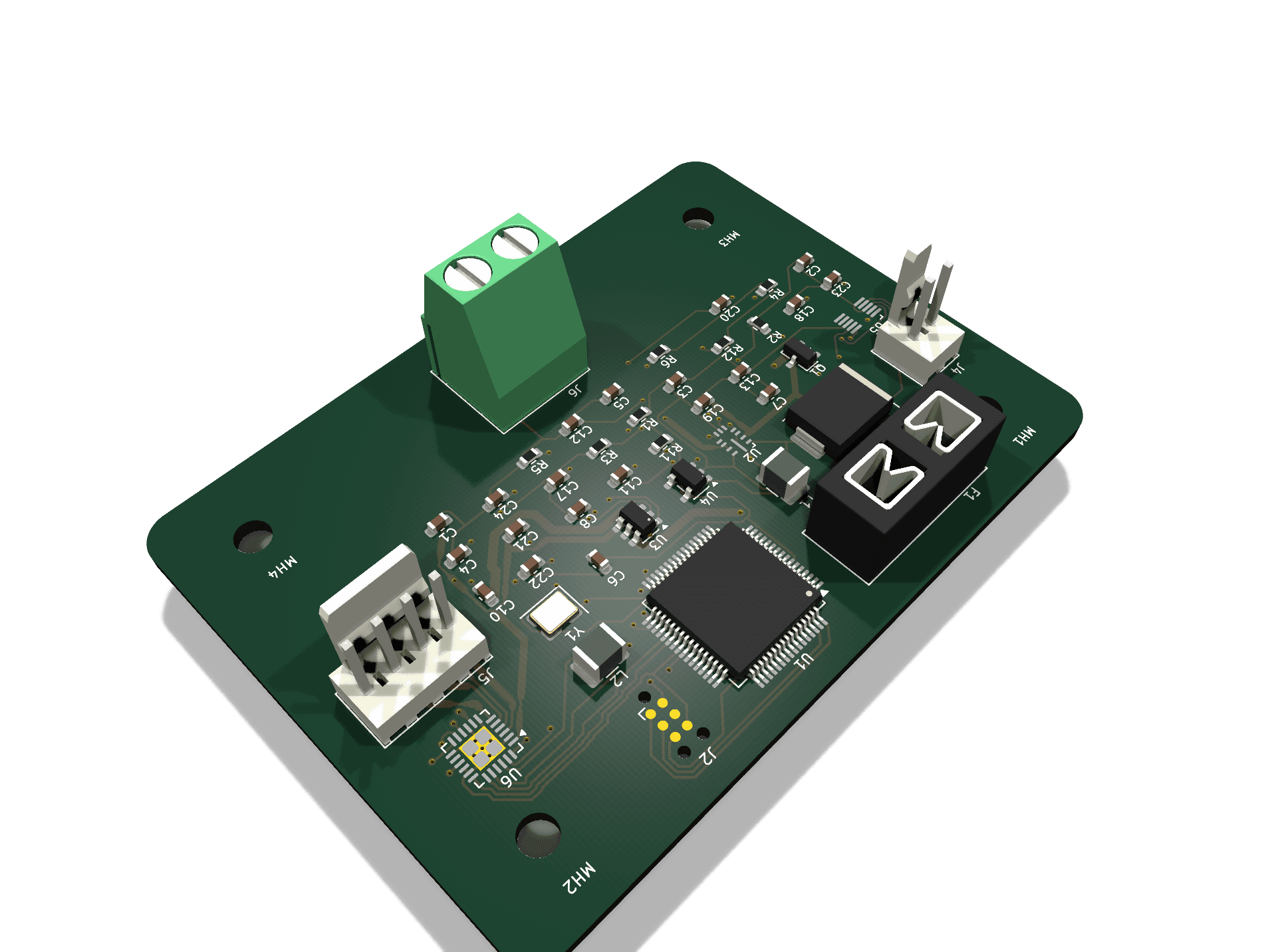
Thermo PCB, isometric render, top side populated
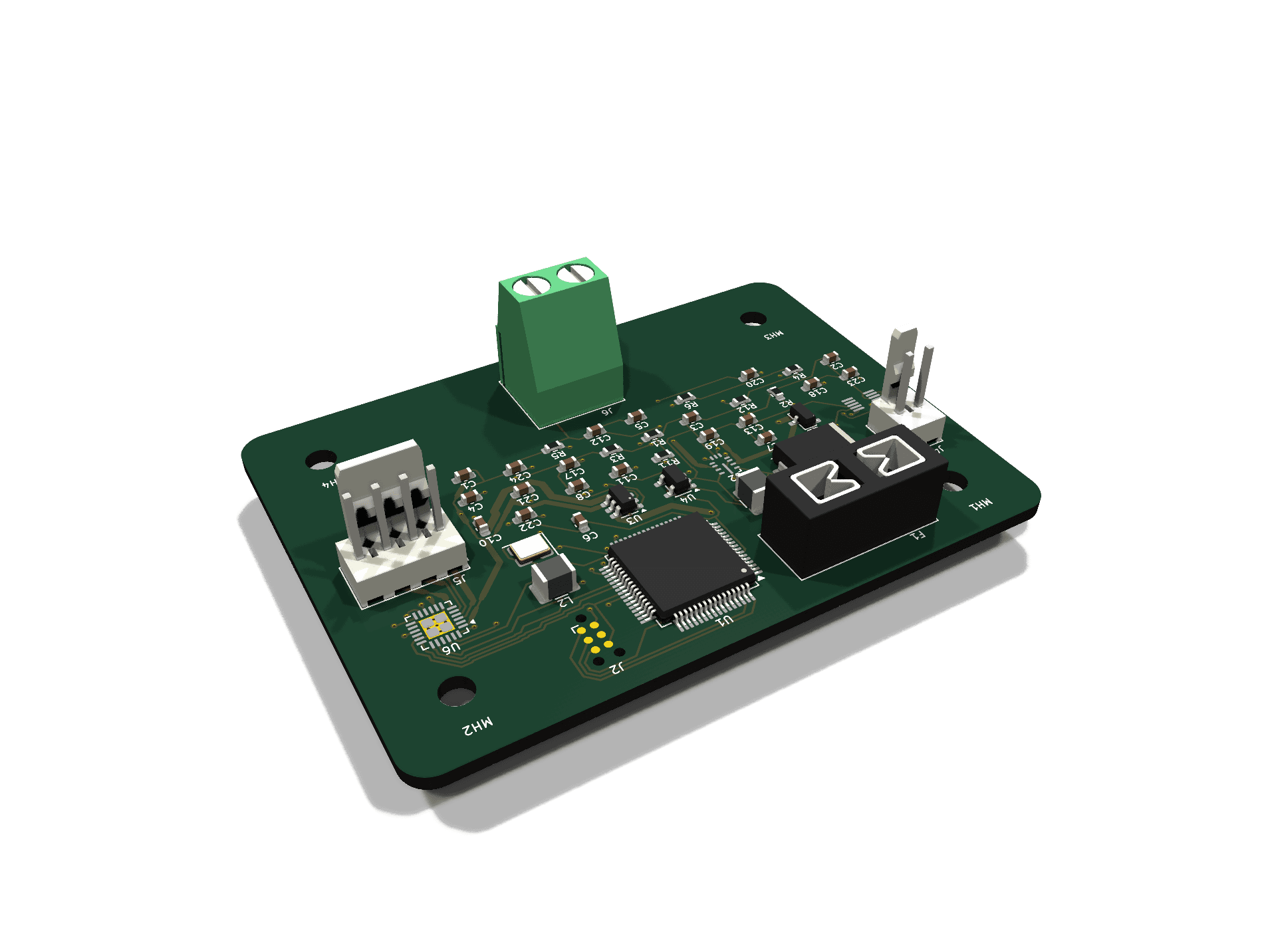
Thermo PCB, second isometric angle
Populated top side, low angle
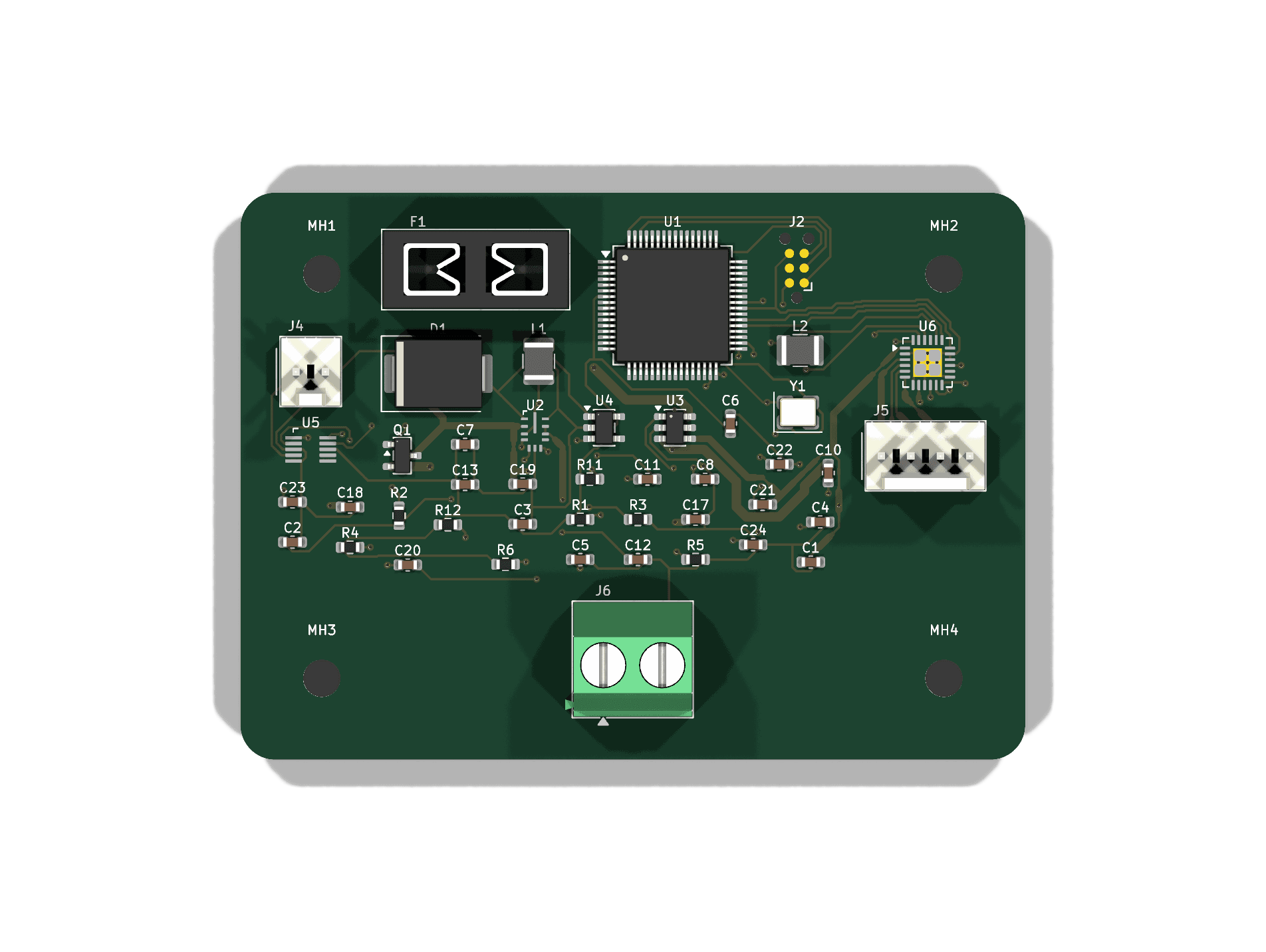
Thermo PCB, straight top-down view with silkscreen references visible
Top-down — reference designators visible
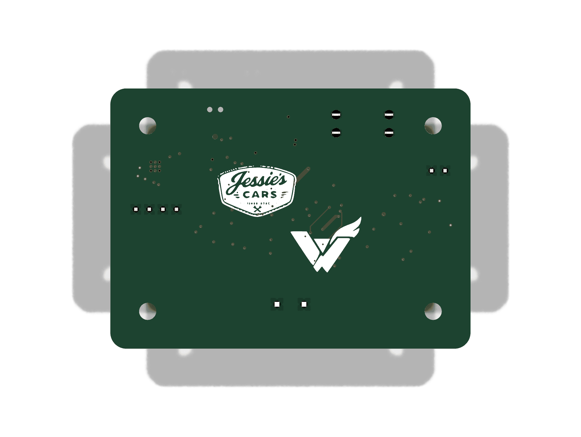
Thermo PCB back side, showing mounting holes and back silkscreen logo
Back side — mounting holes, no components

Wiring the harness

Every off-board connection on Thermo is a short pigtail: a sealed Deutsch DTM06 connector on the outboard (engine-bay) end, wired to one of the four board-mount connectors below. None of the DTM06 housings mount to the PCB directly — they live on the free end of the wire.

J6Power Input

Board side: Phoenix Contact MKDS 1,5/2-5,08 (ord. 1715721), 5.08 mm screw terminal · Outboard end: Deutsch DTM06-2S, nickel contacts

PinNetFunction
1VIN+12V, engine-bay battery rail (fused & reverse-battery protected on-board)
2GNDChassis / battery return

Protected by F1, a 2A Littelfuse 297-series MINI blade fuse (SAE J2077 / ISO 8820-3) in a standard replaceable holder — swap it with any auto-parts-store blade fuse. Reverse-battery protection is a real ideal-diode stage (TI LM74700-Q1), not just a series diode, so there's no forward-voltage drop to budget for.

J4Temperature Sensor Input

Board side: Molex KK-254 22-27-2021, 2.54 mm friction-lock · Outboard end: Deutsch DTM06-2S, nickel contacts

PinNetFunction
1TSENSESensor signal lead — resistive divider node (R12 pull-up to +3V3)
2GNDSensor return lead

Real automotive resistive temp sending unit (GM-style closed-element NTC, via DIYAutoTune, 3/8" NPT, 2-wire isolated, −40°F–210°F). No polarity to worry about — it's a plain 2-terminal resistor, so the two leads are interchangeable, unlike the K-type thermocouple this input used to carry. Feeds U5 (ADS1118-Q1) AIN0 as a simple resistive divider (R12 = 1.00kΩ, chosen to center ADC resolution on the sensor's real 86–210°F operating range) — firmware needs a resistance-to-temperature lookup against the sensor's published curve (−40°F=100.7kΩ, 86°F=2.24kΩ, 210.2°F=177Ω), not a linear formula.

J5Stepper Output

Board side: Molex KK-254 22-27-2041, 2.54 mm friction-lock · Outboard end: Deutsch DTM06-4S, nickel contacts

PinNetFunction
1AOUT1Motor coil A, terminal 1
2AOUT2Motor coil A, terminal 2
3BOUT2Motor coil B, terminal 2
4BOUT1Motor coil B, terminal 1

Driven by U6 (DRV8434A-Q1), current-limited to 1.50 A/phase by an on-board VREF divider (R4 = 1.00kΩ, R5 = 1.50kΩ), matched to the specified motor (StepperOnline 14C19S1504GF5-025RS, 1.5 A/phase) rather than the driver's own 2.5A ceiling. Identify your motor's two coil pairs with a multimeter continuity check before wiring — each coil reads as a low-resistance loop; two leads from different coils read open. Within a coil, lead order only flips that phase's direction (harmless); mixing leads between coils will make the motor stall instead of step. Note the B pair runs 2-then-1: J5's order follows the driver's own physical pad order (U6 pins 3-6 are AOUT1, AOUT2, BOUT2, BOUT1 along its edge), so the four phase traces stay straight and non-crossing. Both pins are still coil B — only that coil's direction flips.

J2SWD Programming

Tag-Connect TC2030-IDC-NL, 6-pin pogo, no header to solder

PinNetFunction
1SWDIOSerial wire data
2VCC+3V3 target reference (not a supply pin)
3SWCLKSerial wire clock
4NCSpare — was BOOT0 on this footprint's original STM32 use, no S32K1 equivalent
5RESETMCU reset, active low
6GNDGround reference

Programmed via NXP's S32 Design Studio + SDK over SWD — the "Arduino-style" heritage of this board family is physical footprint only, there's no Arduino IDE / sketch flow on this MCU.

Bill of Materials

Every part that actually populates the board — 44 placements across 30 orderable line items. Passives are grouped by real value; each semiconductor and connector is a distinct real part, not a placeholder.

30Line items
44Placements
8Semiconductors
28Passives
4Connectors
RefQtyPartDescriptionMfr / PkgQualification
Semiconductors
U11NXP S32K144Arm Cortex-M4F MCU, LQFP-64, 10×10mm, 0.5mm pitch—AEC-Q100
U21TI LMR33630-Q15V synchronous buck converter, VQFN-HR-12 (RNX0012C)—AEC-Q100 G1
U31TI LM74700-Q1Ideal-diode reverse-battery controller, SOT-23-6—AEC-Q100 G1
U41TI TLV733P-Q13.3V LDO, SOT-23-5—AEC-Q100 G1
U51TI ADS1118-Q116-bit SPI ADC w/ PGA, resistive temp-sensor front-end, VSSOP-10 (DGS0010A)—AEC-Q100 G1
U61TI DRV8434A-Q1Stepper motor driver, integrated current sense, VQFN-24 (RGE0024N)—AEC-Q100
Q11Nexperia PMV37ENEAN-channel MOSFET, reverse-battery protection, SOT-23—AEC-Q101
D11SMCJ33ATVS diode, 33V, transient protection, SMC—AEC-Q101
Resistors — 0603
R4, R1221.00kΩMotor VREF divider upper (R4) & TSENSE pull-up (R12) — same value, unrelated circuits—AEC-Q200
R511.50kΩVREF divider, lower — self-calculated, sets IFS=1.50A for the real motor—AEC-Q200
R1, R2, R6, R11410kΩPull-ups (RESET, buck FB reference, U6 nFAULT, U5 SPI_CS)—AEC-Q200
R312.49kΩBuck feedback divider, lower—AEC-Q200
Capacitors — 0603, X7R
C6, C7, C10, C11, C13, C246100nFDecoupling / charge-pump / TSENSE smoothing—AEC-Q200
C17, C18210nFU6 VM decoupling—AEC-Q200
C1, C19210µFInput protection bulk / U6 VM bulk (self-selected)—AEC-Q200
C4, C5218pFY1 crystal load caps—AEC-Q200
C2311nFU6 TRQ_CNT/STL_TH, required regardless of mode—AEC-Q200
C3, C8, C1231µFLDO output / VDDA / VCC decoupling—AEC-Q200
C211220nFU6 charge pump, VCP–VM—AEC-Q200
C20122nFU6 charge pump, CPH–CPL—AEC-Q200
C2122µFBuck output bulk—AEC-Q200
C221470nFU6 DVDD bypass—AEC-Q200
Inductors
L1110µHBuck power inductor, 1210—AEC-Q200
L21Ferrite beadVDDA filter, 1210—AEC-Q200
Electromechanical
F11Keystone 3568 + Littelfuse 297Mini blade fuse holder (THT) + 2A replaceable fuse, SAE J2077 / ISO 8820-3——
Y118MHz crystalSMD, 3225 4-pin—AEC-Q200
Connectors — board side
J21Tag-Connect TC2030-IDC-NLSWD programming, 6-pin pogo——
J41Molex 22-27-2021KK-254, 2-pos — temp sensor pigtail landing——
J51Molex 22-27-2041KK-254, 4-pos — stepper pigtail landing——
J61Phoenix Contact 1715721MKDS 1,5/2-5,08 screw terminal — power pigtail landing——

Not included above (see the connector cards higher up this page): the real automotive temp sending unit itself (GM-style closed-element NTC via DIYAutoTune) and the outboard Deutsch DTM06 housings/contacts that complete each pigtail (all nickel now — J4 downgraded from gold once the sensor stopped being a raw mV thermocouple signal), and the 4× M3 mounting-hole hardware (MH1–MH4, unpopulated NPTH). Y1's 8MHz value and F1's holder/fuse split are generic-part placeholders, not vendor-locked — substitute freely as long as ratings match.